Calibrating an arm - SBP
Introduction
Strip the Instrument as described in Dismantling a Pressuremeter – SBP until the arms are exposed and are free to move. Secure the Pore Pressure Cells in the instrument using a cable tie or PVC insulation tape.
If the arms are to be calibrated after a series of tests then calibrate immediately, because it is important to know the calibrations for the tests that were made. If not, then consider whether the arms and their location slots should be cleaned and restored to pristine condition first.
The arms are numbered sequentially. Arm 1 is in-line with the cable coupling to the instrument. The numbering continues clockwise looking down the instrument.
Calibrating an arm results in information about three parameters:-
-
The sensitivity of the arm, in terms of millivolts of output per millimetre.
-
The linearity of the arm, meaning the variation in sensitivity expressed as a percentage of the average sensitivity.
-
The hysteresis performance of the arm. For every setting of the micrometer two outputs are recorded during the calibration procedure. The first is recorded when the arm is moving from zero to its maximum setting, the second is obtained when the arm returns from the maximum to the zero position. The difference between these two readings expressed as a percentage of the range covered is a measure of the hysteresis.
Figure 4a-1 shows a guide to the Arm Calibration Jig:
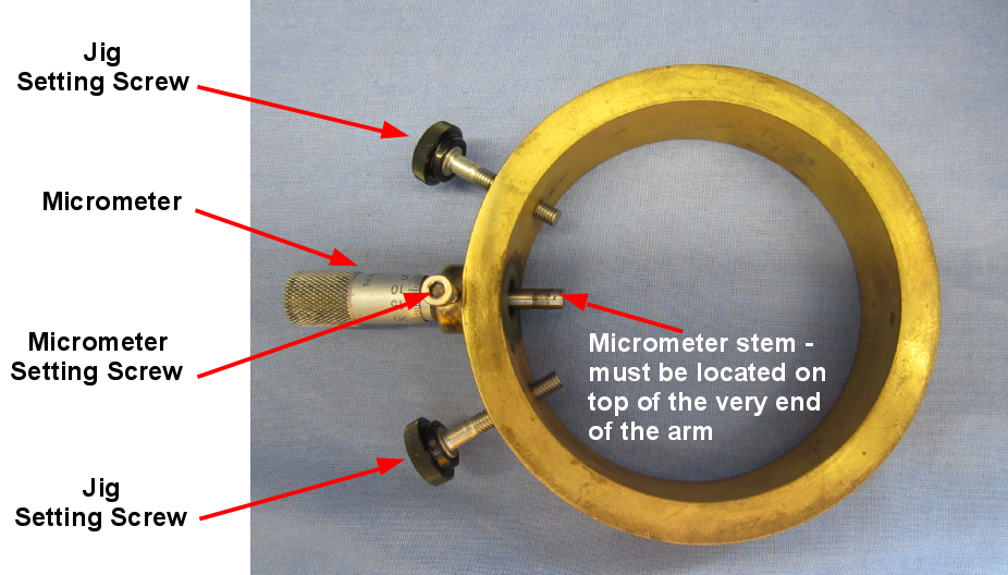
Figure 4a-1 Arm Calibration Jig SBP
Arm calibration procedure
The steps are as follows:
-
Place the jig over an arm, fixing the jig to the body of the instrument using the jig setting screws. Ensure that the micrometer setting screw is initially loose. It is recommended to rotate the instrument in the clamp such that the arm travel is not vertical i.e. the micrometer is pointing away from you at an angle. Figure 4a-2 shows the jig installed and the instrument at a suitable rotation.
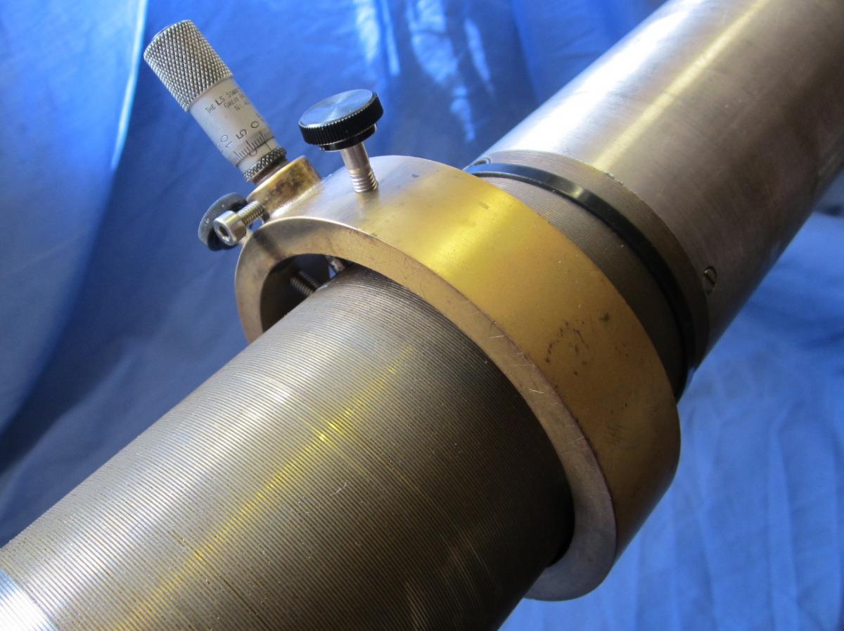
Figure 4a-2 Placement of jig and instrument
-
Let the stem of the micrometer come into contact with the arm, making sure that the stem lies centred on top of the very end of the arm – it is this part of the arm that follows the movements of the membrane. See Figure 4a-3.
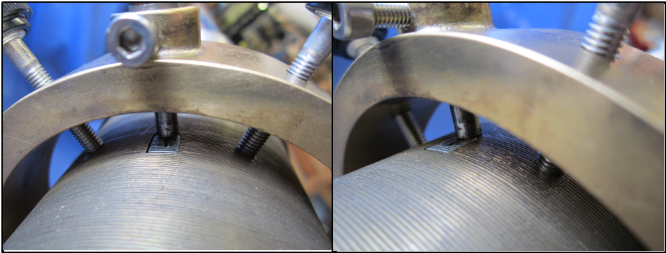
Figure 4a-3 Locating the micrometer stem
-
Adjust the position of the jig until everything is correct. Now set the micrometer to zero; push the arm to its zero position with the stem of the micrometer and fix the micrometer with the micrometer setting screw. Now 'zero' on the micrometer is the same as the starting position of the arm. See Figure 4a-4.
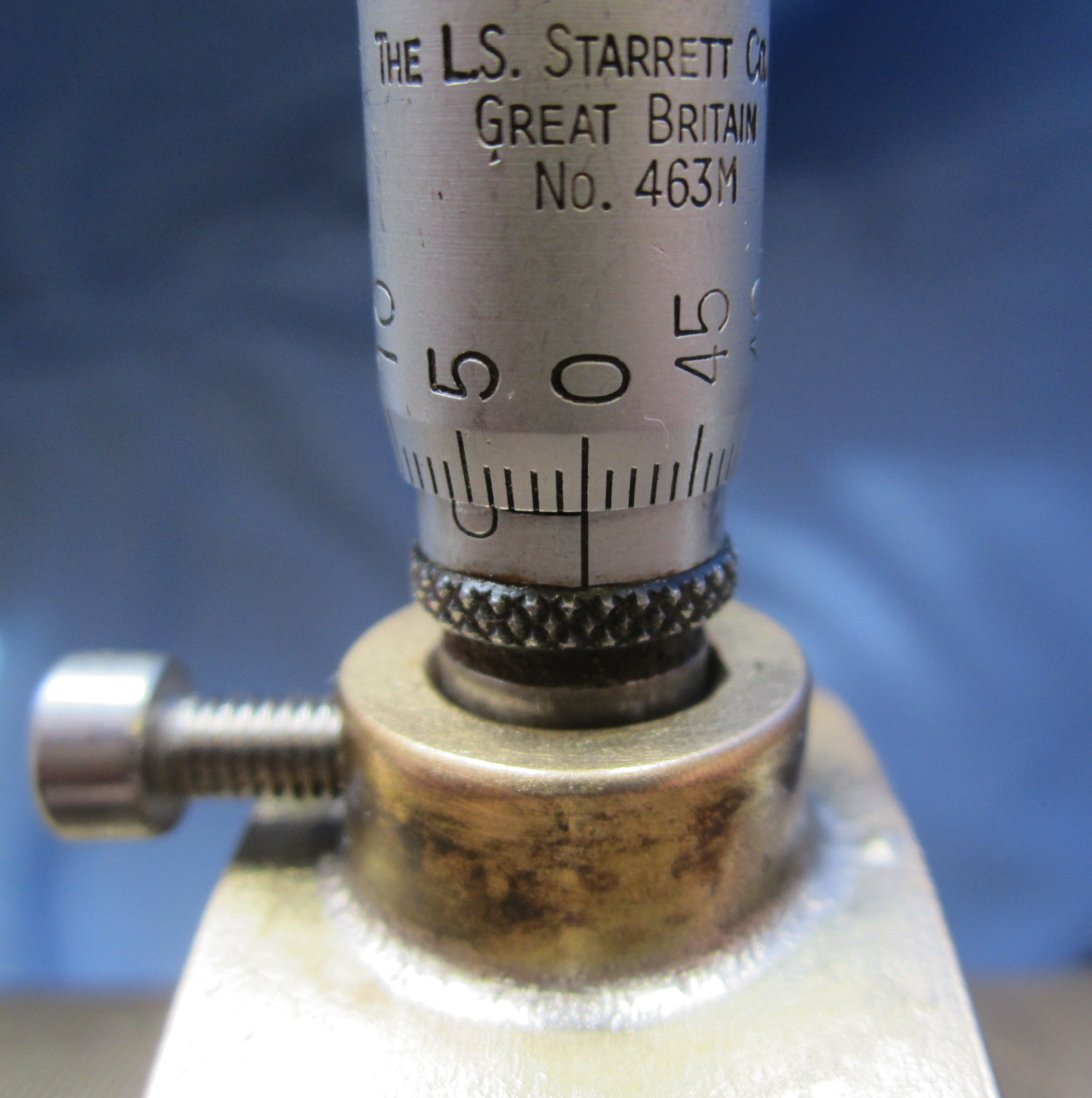
Figure 4a-4 Zero
-
Unwind the micrometer checking that the arm is moving freely. Return it to the zero position.
-
Referring to Figure 4a-5 make the following electrical connections:-
-
Connect the Gas-to-Electricity Separating Union (A) to the PRESSUREMETER socket (B) on the Electronic Interface Unit (C).
-
Connect the BATTERY socket (D) on the EIU to a 12 volt battery.
-
Connect one of the RS232 sockets on the EIU (E) to the serial port of the PC/laptop. Most modern laptops will require a USB to Serial adapter (F).
-
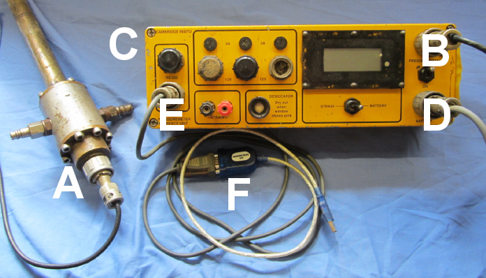
Figure 4a-5 Electrical connections for calibration procedure
-
Switch the EIU and PC/laptop ON. Open the WINLog application and click Test >> Configure probe to select either a 3 or 6 arm Self Boring Pressuremeter and to set the COM port for your system. Click OK. See Figure 4a-6.
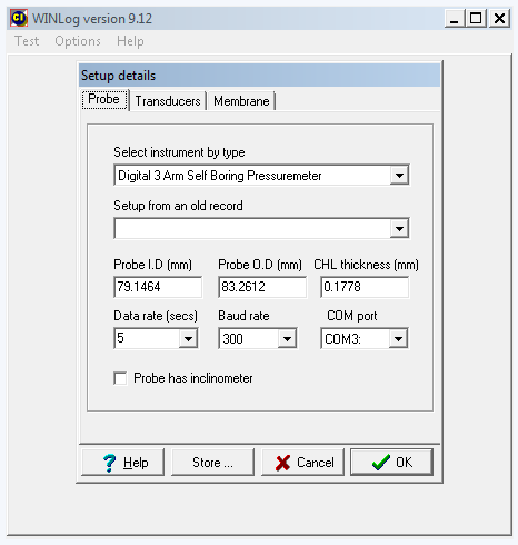
Figure 4a-6 WINLog probe setup
-
Now click Test >> Display raw data.
-
WINLog will display the output of the pressuremeter transducers shown as a row of numbers in volts. The display will update on a short cycle depending on the type of pressuremeter. Leave the system running for a short while until the readings are steady. See Figure 4a-7.
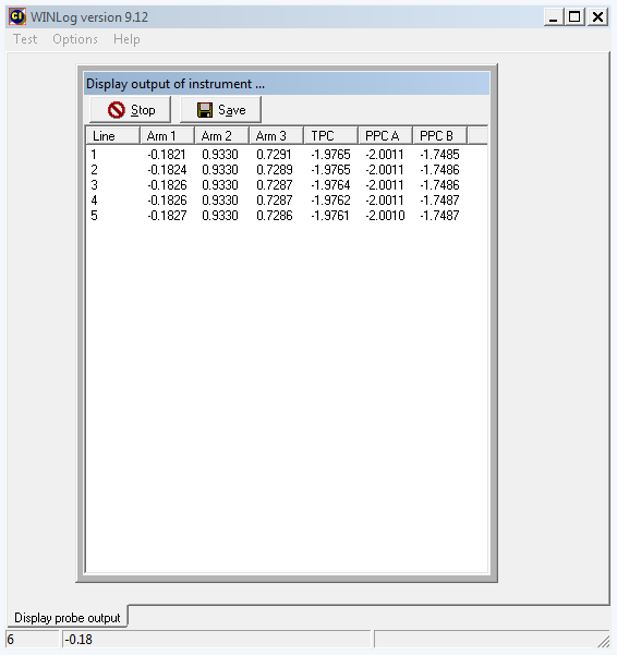
Figure 4a-7 WINLog instrument readings
-
Using the appropriate calibration sheet (available here: Calibration Sheets) write down the zero reading for the arm being calibrated. The readings should be recorded in millivolts in the calibration sheet.
-
Now carefully wind the micrometer out and set to 1 millimetre. It is important that the micrometer be set exactly on 1 millimetre without overshooting and then being turned backwards. Overshoot and subsequent adjustment will spoil any attempt to measure the hysteresis performance.
-
When the next line of data appears on the screen write down the value.
-
Continue incrementing the micrometer in 1mm steps and writing down the readings until the arm has reached a deflection of 6 millimetres.
-
Now reverse the procedure, coming down in exactly the same steps of 1 millimetre.
-
Repeat the calibration procedure on the other arms.
-
When readings have been obtained for all arms click the Save button to save the raw calibration data in an appropriately named file.
-
After verifying the contents of the saved file click the Stop button to stop WINLog capturing raw data.
-
Switch off the EIU.
-
Sign and initial the calibration sheet – this can be scanned and saved with the raw data to provide an audit trail of the calibration.
Once the raw calibration data are obtained then they can be converted to parameters in a number of ways.
Refer to Using a spreadsheet to derive calibration factors for a description of the use of a spreadsheet to manipulate the numbers.